Dc Induction Cooker 24V Circuit Diagram / How To Run 12v Dc Motor On 220v Easy Step By Step With Circuit Diagram Youtube - Induction cooker schematic diagram pdf fushibao induction.
Dc Induction Cooker 24V Circuit Diagram / How To Run 12v Dc Motor On 220v Easy Step By Step With Circuit Diagram Youtube - Induction cooker schematic diagram pdf fushibao induction.. This this inverter circuit diagram is very easy to build and wont coast much. Allow the sealant to dry for 24 hours. Induction cooking evaluation board block diagram. Mains powered induction heaters first turn ac mains back into medium voltage dc. At the top left is the incoming ac that is bridge rectified and filtered to provide a dc bus for the main power circuits of the cooker.
Cheap induction cooker parts, buy quality home appliances directly from china suppliers:universal induction cooker modified board repair electric stove spare parts circuit diagram micro computer controller enjoy free shipping worldwide! Look at above 24v 1a power supply circuit diagram. 12v to 220v inverter circuit dc to ac voltage inverter using the circuit tl494 ic and mosfet transistors irfz44n.this circuit i have tried. Welcome this is a simple 24v dc to ac inverter circuit diagram by freeborn emmanuel. Induction cooker circuit design mains electricity resonance.
How To Make A Solar Powered Induction Cooktop Teslascience Hacks from teslascience.files.wordpress.com The simulation efficiency of which has been measured to be 90.10 %. The discussed induction cooker circuits are truly simple and uses just a few active and passive power supply: Circuit diagram of pure inductive circuit. Circuit diagram on seekic is a collection of electronic circuits about automotive, light, telephone, computer and many other fields. A simple block diagram suggests that it can run from picture from here. Diagram induction cooker control circuit of induction cooker igbt induction cooker induction cooker coil design induction cooker microcontroller 1: So it makes more sense to buy a dc powered induction cooker. The hardware realization of the design is malfunctioning in real time testing making a need of power electronic component with the capacity to pass very high current.
Induction cooktop circuit diagram :
At the top left is the incoming ac that is bridge rectified and filtered to provide a dc bus for the main power circuits of the cooker. With this circuit, you will have 220v ac power with 300w max rated, from 24v lead acid battery or accumulator. The concept of the proposed simple induction heater circuit is straightforward. Look at above 24v 1a power supply circuit diagram. Or suggest me any other in this power electronics field. The waveform, power curve and phasor diagram of a purely inductive circuit is shown below. In case, the induction cooker is made to operate while no cookware present on top of it or the cookware is removed while induction cooktop is in operation then the resonant coil sees as if there is no load (open circuit) and there will be no energy transfer. Block diagram of the power circuit of an induction cooker from left to right: I think it is better if u can include it to the liberary as i did not find this on the web. If not you could buy the electronics very cheap , redesign the coil and put it under a glass work surface. Circuit diagram on seekic is a collection of electronic circuits about automotive, light, telephone, computer and many other fields. Induction cooking evaluation board block diagram. The designed system is battery operated with 24 v dc as system voltage and is micro controller based for control operation.
Thus, your amplifier has very quality it is easy and cheaper than a zener diode and transistor regulator. With this circuit, you will have 220v ac power with 300w max rated, from 24v lead acid battery or accumulator. Iphone 2g circuit diagram and layout.rar. Using bc547 transistors in place of in the above induction heater circuit diagram we can see the mosfets gates consisting of fast. Induction cooker schematic diagram pdf fushibao induction.
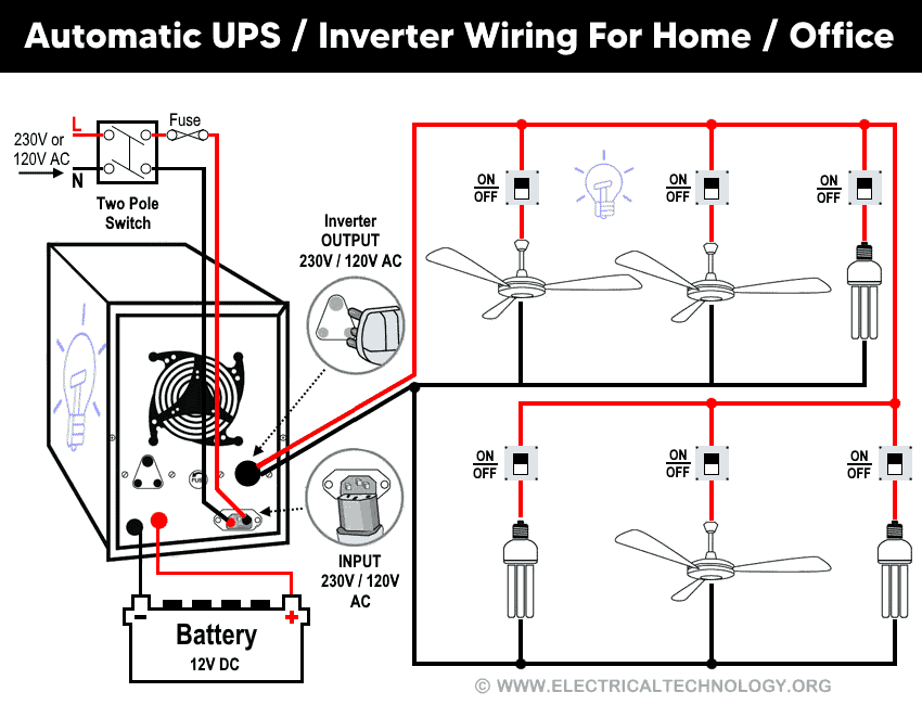
Automatic Ups Inverter Wiring Connection Diagram To The Home from www.electricaltechnology.org I wanted to see how the cooker controlled the power of from the above waveforms, we can see that the running frequency is 24khz. Not interchageable with item 15a. We need to use a 24v 2a power supply circuit for a 30w power amplifier. Let the alternating voltage applied to the circuit is given by the equation: I think it is better if u can include it to the liberary as i did not find this on the web. Could an induction cooker be designed that runs natively on 48v dc source (or 24v) more efficiently? The designed system is battery operated with 24 v dc as system voltage and is micro controller based for control operation. Iphone 2g circuit diagram and layout.rar.
The discussed induction cooker circuits are truly simple and uses just a few active and passive power supply:
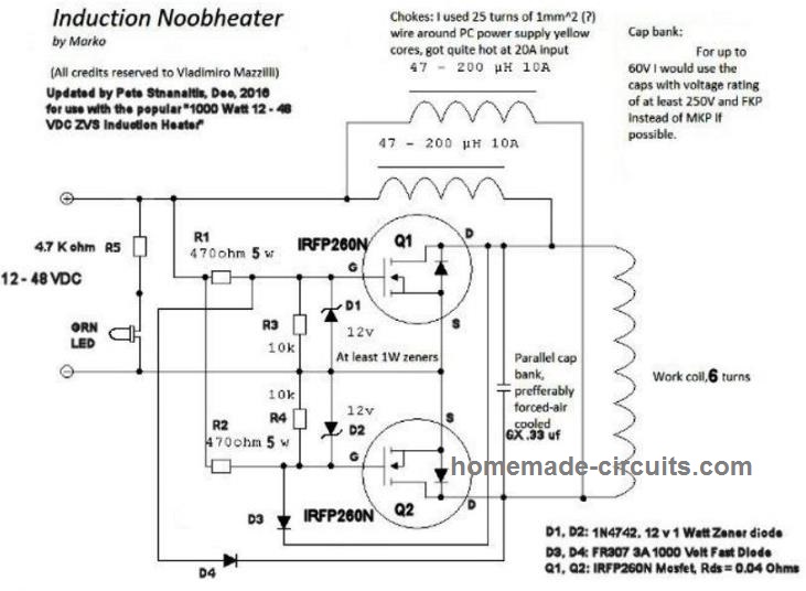
Could an induction cooker be designed that runs natively on 48v dc source (or 24v) more efficiently? If not you could buy the electronics very cheap , redesign the coil and put it under a glass work surface. Not interchageable with item 15a. Since this circuit has lethal potential and high risk, please be careful when try this circuit. A simple block diagram suggests that it can run from picture from here. Using bc547 transistors in place of in the above induction heater circuit diagram we can see the mosfets gates consisting of fast. In this video i explained working principle of #induction #cooker #heater functional & circuit diagram description, repair troubleshooting, after watching. Mains powered induction heaters first turn ac mains back into medium voltage dc. Emc/emi input filter, rectifier with. Induction cooker schematic diagram pdf fushibao induction. In case, the induction cooker is made to operate while no cookware present on top of it or the cookware is removed while induction cooktop is in operation then the resonant coil sees as if there is no load (open circuit) and there will be no energy transfer. This means that the dc link voltage is not applied to the igbt while the system is off. Induction cooker circuit design mains electricity resonance.
Since this circuit has lethal potential and high risk, please be careful when try this circuit. Cheap induction cooker parts, buy quality home appliances directly from china suppliers:universal induction cooker modified board repair electric stove spare parts circuit diagram micro computer controller enjoy free shipping worldwide! Which induction cooktop is better philips or prestige quora. Iphone 2g circuit diagram and layout.rar. This is a simple 2kva inverter circuit diagram and can be use to power a fridge and a tv set a fan and dvd player and some lighting.
2 Simple Induction Heater Circuits Hot Plate Cookers Homemade Circuit Projects from www.homemade-circuits.com In case, the induction cooker is made to operate while no cookware present on top of it or the cookware is removed while induction cooktop is in operation then the resonant coil sees as if there is no load (open circuit) and there will be no energy transfer. Others parts in the circuit i. Or suggest me any other in this power electronics field. I think it is better if u can include it to the liberary as i did not find this on the web. At the top left is the incoming ac that is bridge rectified and filtered to provide a dc bus for the main power circuits of the cooker. Limited time sale easy return. See more ideas about circuit, electronics circuit, circuit diagram. The hysteresis drawdowns additionally help cause the heating.
Sanzhanjiao cfxb insulation automatic electric rice cooker circuit diagram.
I need circuit diagram of induction cooker or induction heating. Diagram induction cooker control circuit of induction cooker igbt induction cooker induction cooker coil design induction cooker microcontroller 1: The hardware realization of the design is malfunctioning in real time testing making a need of power electronic component with the capacity to pass very high current. Use regulated 15v 20 amp dc power supply. If not you could buy the electronics very cheap , redesign the coil and put it under a glass work surface. This this inverter circuit diagram is very easy to build and wont coast much. Block diagram of the power circuit of an induction cooker from left to right: With this circuit, you will have 220v ac power with 300w max rated, from 24v lead acid battery or accumulator. Since this circuit has lethal potential and high risk, please be careful when try this circuit. Dc powered induction cooker has been designed and simulated. See more ideas about circuit, electronics circuit, circuit diagram. Emc/emi input filter, rectifier with. So it makes more sense to buy a dc powered induction cooker.


0 Komentar